Greatest Mass Air Flow Sensor Diagram of all time Don't miss out!
VIEW MY OTHER CHANNEL JOE ELECTRONICS SCHEMATICS FOR AUTO FOR OTHER VIDEOS WITH AUTOMOTIVE DIAGNOSTICS AND WIRING DIAGRAMS Mass air flow sensor , theory and diagnostics from wiring.
Mass Air Flow Sensor Wiring Diagram Diagram Stream
The mass air flow sensor wiring harness is an essential component in a vehicle's engine management system. It connects the mass air flow sensor to the engine control unit, allowing for the accurate measurement of the amount of air entering the engine.

Nissan Mass Air Flow Sensor Wiring Diagram Eco Yard
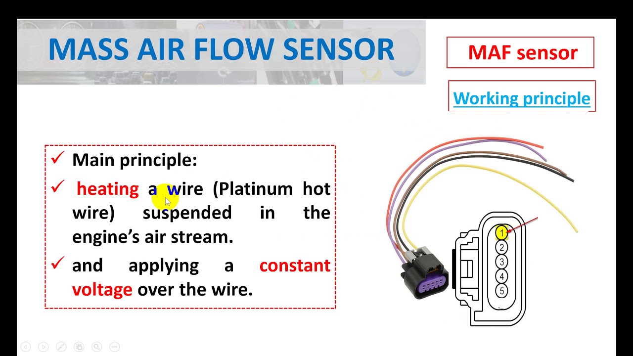
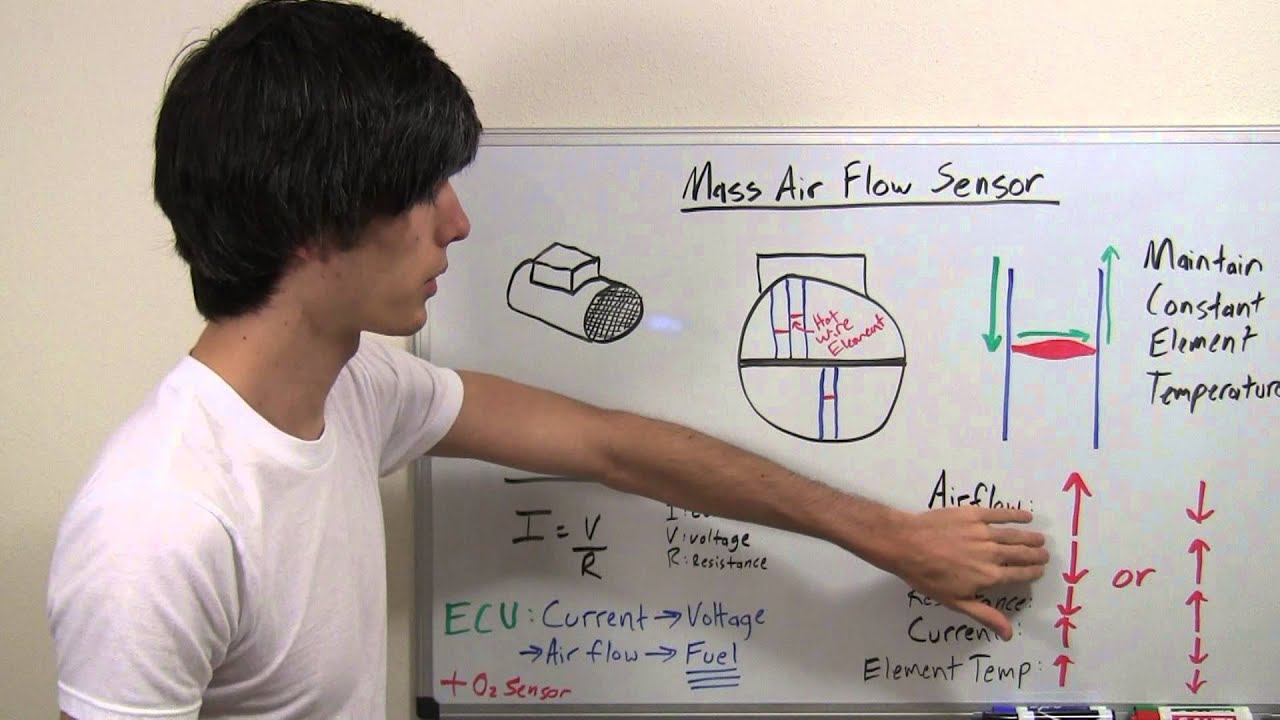
See the diagram. The mass air flow sensor measures the amount of air entering the engine or the air flow. In modern cars, an intake air temperature or IAT sensor is built in the mass air flow sensor. There are few types of air flow sensors, however, modern cars use a hot-wire type. Let's see how it works. How a hot-wire air flow sensor works
Mass Airflow Sensor Wiring Diagram Needed I Pulled Off The Wiring My
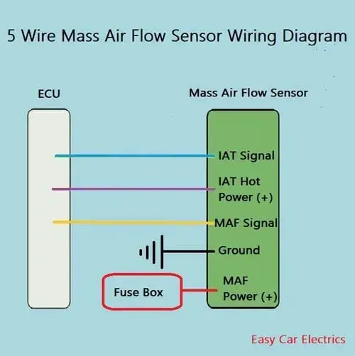
The 5 pin mass air flow sensor works by using the amount of air entering the engine to measure the mass of the air, allowing the engine to adjust the fuel-air mixture accordingly. The 5 pin mass air flow sensor is composed of a hot wire, a ground wire, an air flow control valve, and two additional wires for the control circuit.
3 Wire Mass Air Flow Sensor Wiring Diagram
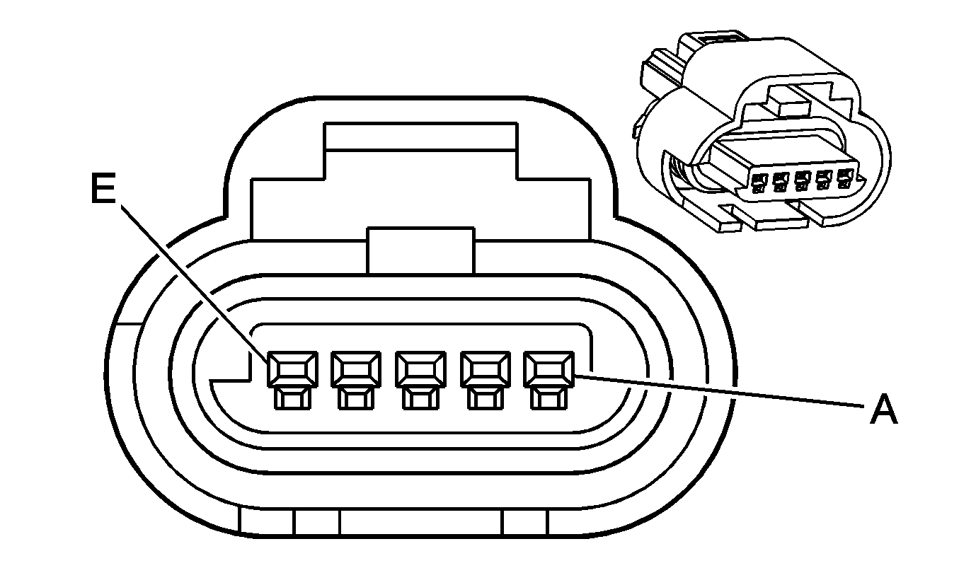
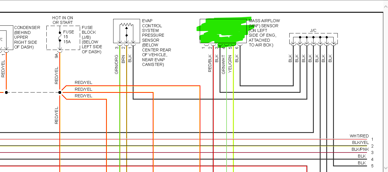
The MAF sensor wiring diagram consists of five wires. The wires may vary in color, but all of them are typically labeled with numbers. The first wire is the power wire, which is usually labeled "12V" for 12 volts. This wire provides power to the MAF sensor. The second wire is the ground wire, which is labeled "GND" for ground.

LS Mass Air Flow Connector 5 Wire Harness Pigtail Gen 3 MAF Auto Parts
The wiring diagram for the Nissan mass air flow sensor typically includes information about the sensor's power source, ground, and the signal wire. The power source provides voltage for the sensor's operation, while the ground ensures a proper return path for the electrical current. The signal wire carries the voltage output from the MAF.
4 Pin Maf Sensor Wiring Diagram / Air Flow Wiring Diagram If the maf
A Comprehensive Wiring Diagram - Wiring mass air flow sensors doesn't have to be complicated. Our comprehensive wiring diagram will guide you through the process for 3, 4, and 5 wire sensors. Get started now! Team Tech Advice from Car Electronics Experts - CarElectronix.com.
5 pin mass air flow sensor wiring diagram [2022]
How To Test The GM Mass Air Flow Sensor (Early Type): Buick, Chevy, Olds, Pontiac 3.1L, 3.4L, 4.3L, 5.0L, 5.7L V6 Engines (1996-2005) How To Test The GM MAF Sensor: Buick, Chevy, Olds, Pontiac 3.8L V6 Engines (1996-2005) How To Test The MAF Sensor on 3.1L, 3.3L, and 3.8L Buick, Oldsmobile, Pontiac (1988-1996) Symptoms Of A Bad GM MAF Sensor

Mass Air Flow Sensor Wiring Diagram Diagram Stream
The MAF (Mass Air Flow) sensor is an important component in the engine management system of a vehicle. It measures the amount of air entering the engine to determine the correct fuel-to-air ratio for optimal combustion. This data is then used to adjust the fuel injection and ignition timing, ensuring optimum engine performance and fuel efficiency.

How to Test a Mass Air Flow MAF Sensor Without a Wiring Diagram YouTube
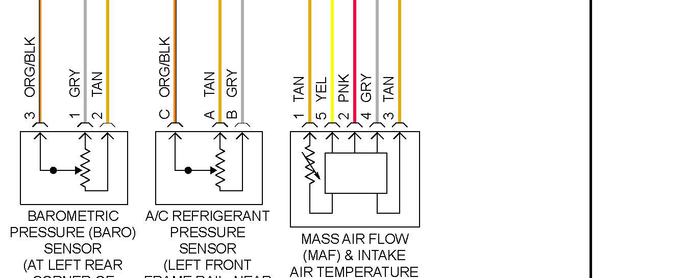
The mass air flow sensor or air flow sensor wiring diagram is designed by the manufacturer according to the year, model, construction, type, and demand. There are 4 forms of air flow sensor wiring diagrams. They are, 3-wire mass air flow sensor wiring diagram (hot wire-reference voltage from ECU, ground wire, signal wire).

3 Wire Mass Air Flow Sensor Wiring Diagram
Tips for Efficiently Installing and Maintaining a 5 Wire MAF Sensor Wiring Diagram. When it comes to installing and maintaining a 5 Wire MAF (Mass Air Flow) sensor wiring diagram, there are a few key tips that can help ensure a smooth and efficient process: 1. Gather the right tools:
Airflow Sander Wiring Diagram Heavy Wiring
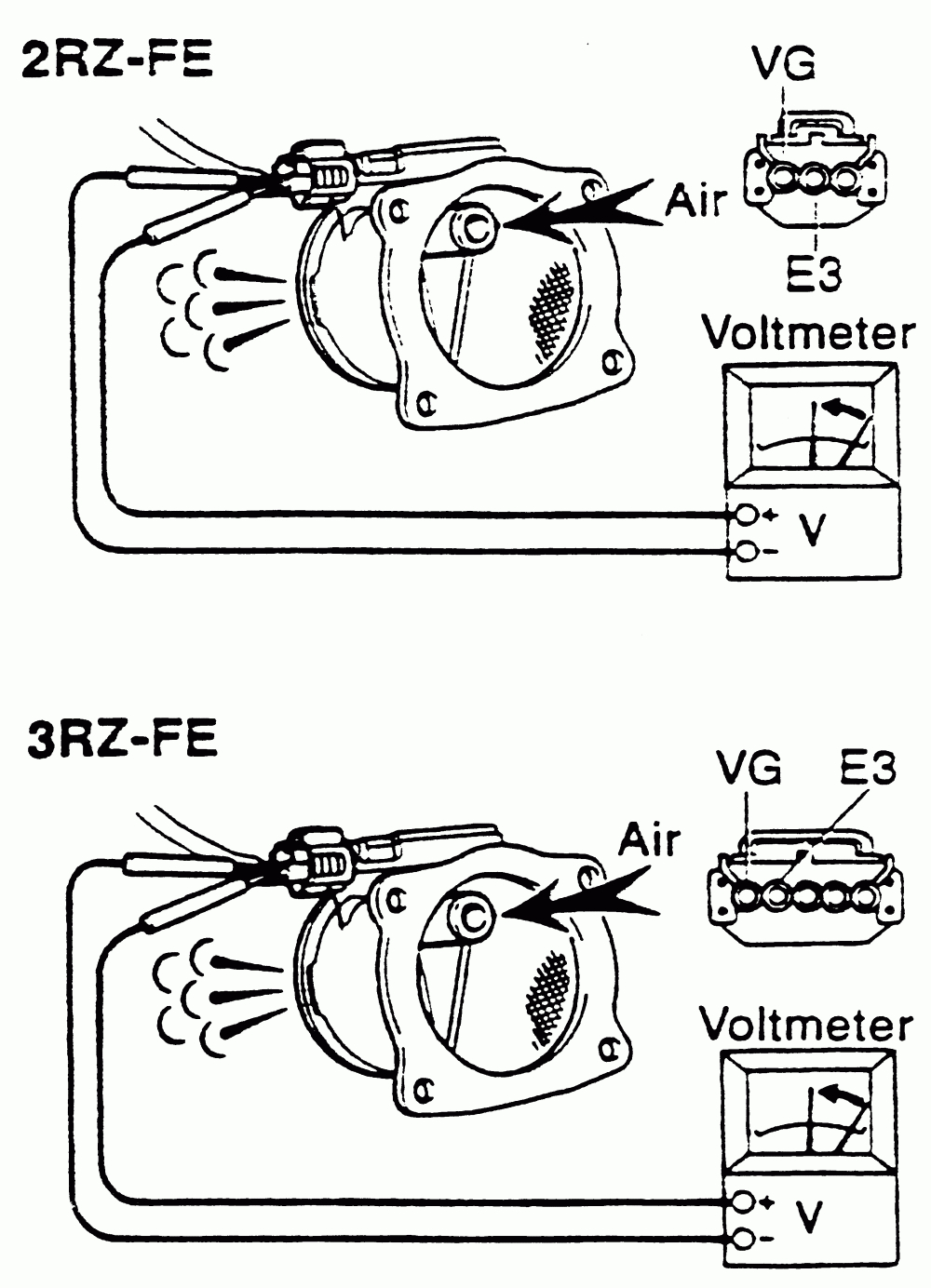
Testing a MAF sensor, whether 3-wire or 5-wire, involves first identifying the power connector, which should give a reading of approximately 12 volts, and the ground connector, which should give a reading of approximately one ohm, and then testing the signal wire according to the type of sensor. I explain the process in more detail below.
Bosch Maf Sensor Wiring Diagram / Mass Airflow Sensors Maf Bosch Auto
The MAF sensor signal is used by the engine control module to calculate the amount of fuel needed for ignition. In winter, the air is denser hence more fuel is injected into the ignition chamber. If the engine gets warmer the gasoline consumption will be less. A mass air flow sensor comes with different numbers of wires.

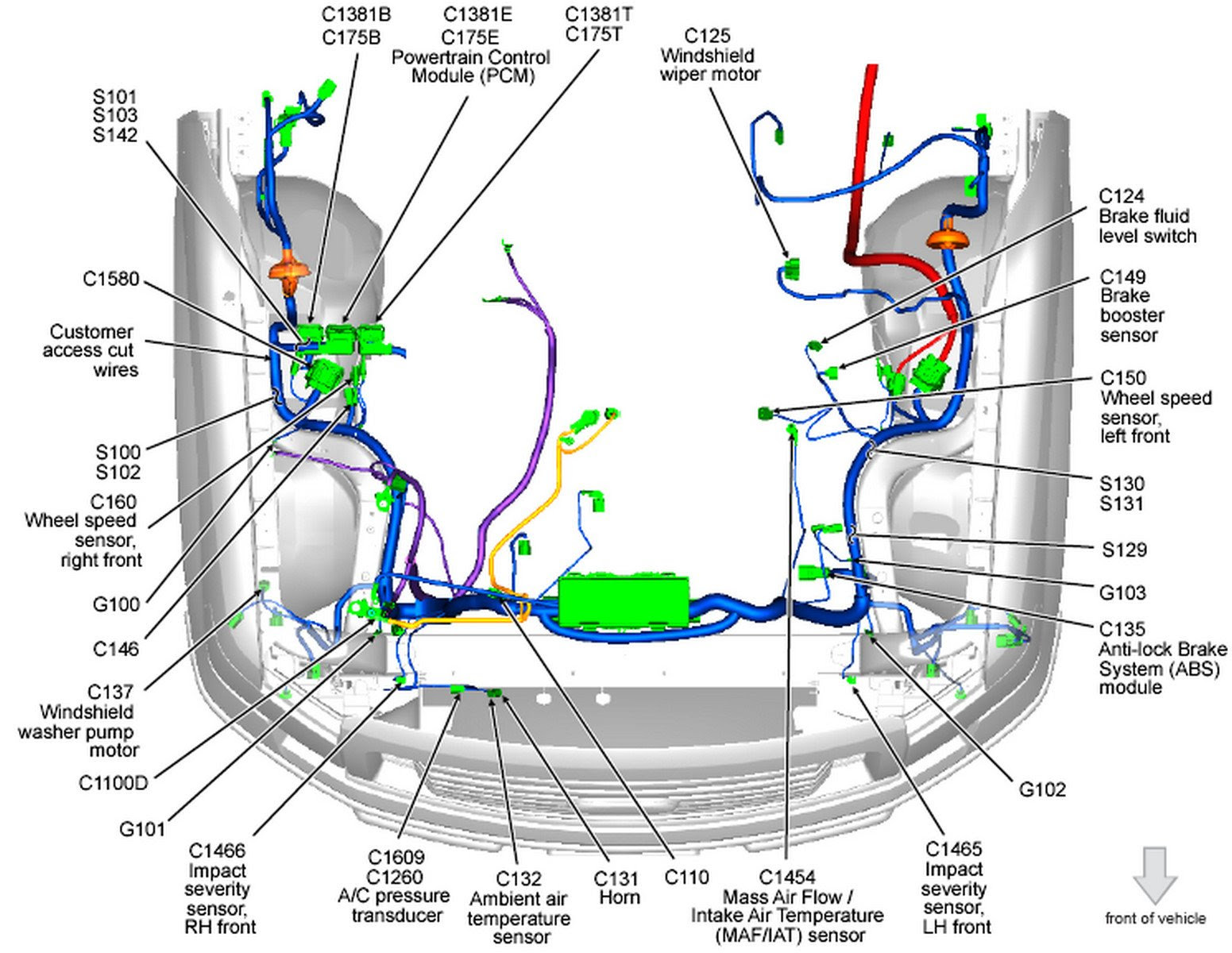
MAF IAT Sensor Wiring Diagram
As the density of air changes across temperature it is logical to include an air temperature sensor as part of the air flow sensor so that the mass of air can be determined (it is the mass of air not the volume that is required for correct AFR calculations). Hot Wire Mass Air Flow Sensor (5 Wire)

[DIAGRAM] 1995 Ford Mustang Maf Wiring Diagrams
The most common way to test the 5 wire VW Mass Air Flow (MAF) sensor is just to unplug it with the engine running. If the MAF is bad (either because it's not producing a signal or producing an erratic one), the car's idle will return to normal and the car will seem to run fine.
nissan maf sensor wiring diagram
In this episode I go over how to convert from the factory 5-wire combination Mass Airflow (MAF)/Intake Air Temperature (IAT) sensor to a stand alone 2-wire I.
